WindowCircleOp offset issue

Posted by Twisol on Sat 28 Aug 2010 08:24 AM — 19 posts, 50,774 views.

USA #0
Using a slightly modified test-grid window as an example:

-- make the visible window
local win = "win"
WindowCreate(win, 0, 0, 200, 250, 12, 0, 0)
WindowCircleOp(win, 2,
  0, 0, 0, 0,
  0, 5, 0, -- no pen
  ColourNameToRGB("saddlebrown"), 0,
  0, 0, 0, 0)

-- draw a grid
for i = 1, math.max(WindowInfo(win, 3), WindowInfo(win, 4)) / 25 do
  WindowLine(win, i * 25, 0, i * 25, WindowInfo(win, 4), 0xC0C0C0, 0, 1)
  WindowLine(win, 0, i * 25, WindowInfo(win, 3), i * 25, 0xC0C0C0, 0, 1)
end -- for

WindowShow(win, true)


The last pixel in each line sticks out beyond the rectangle I drew. But (0,0,0,0) is supposed to mean the whole window area, no? If I use (0,0,201,251) it gets those last pixels, but that's counterintuitive, because the window is supposedly only 200x250.

[EDIT] Using (0,0,1,1) produces nothing. (0,0,2,2) produces a single pixel.

[EDIT] This issue also affects the rounded-rectangle mode of WindowCircleOp, with Extra1 and Extra2 set to 0 (i.e. no rounding). I'm unsure if it affects the other modes, but it's probable...
Amended on Sat 28 Aug 2010 09:05 AM by Twisol
Australia Forum Administrator #1
WindowCircleOp selector 2 calls CDC:Rectangle.

According to the help for that:

Rectangle help said:

The rectangle extends up to, but does not include, the right and bottom coordinates
This means that the height of the rectangle is y2 - y1 and the width of the rectangle is x2 - x1

Both the width and the height of a rectangle must be greater than 2 units and less than 32,767 units.


It may be counter-intuitive, but that is what the underlying API does. I don't want to change it now, but perhaps the help should be changed.
Amended on Sat 28 Aug 2010 09:30 AM by Nick Gammon
Australia Forum Administrator #2
I think it is because rectangles (and circles) are supposed to be enclosed in their boundaries, not hit them.
USA #3
Aah.... Weird. So WindowRectOp and WindowCircleOp use different functions to draw rectangles? :S

Nick Gammon said:
I think it is because rectangles (and circles) are supposed to be enclosed in their boundaries, not hit them.

Hmm, WindowRectOp doesn't do this. :S


Well, as a workaround, setting a solid pen with width 1 and the same color also solves it.
WindowCircleOp(win, 2,
  0, 0, 0, 0,
  ColourNameToRGB("saddlebrown"), 0, 1,
  ColourNameToRGB("saddlebrown"), 0,
  0, 0, 0, 0)

Thanks for the explanation, Nick!
Amended on Sat 28 Aug 2010 04:42 PM by Twisol
Australia Forum Administrator #4
Careful reading of the help for the (Windows) Rectangle function shows this:


This function requires only the coordinates for the upper left and the lower right corners. When an application calls the Rectangle function, the system draws the rectangle, excluding the right and lower sides if no world transformation is set for the given device context.

If a world transformation has been set by using the SetWorldTransform or ModifyWorldTransform function, the system includes the right and lower edges.


My test seems to confirm this:


local win = "win"
WindowCreate(win, 0, 0, 16, 16, miniwin.pos_center_all, 0, ColourNameToRGB "green")
WindowCircleOp(win, miniwin.circle_rectangle,
  4, 4, 10, 10,  -- location
  0, miniwin.pen_null, 0, -- no pen
  ColourNameToRGB("saddlebrown"), miniwin.brush_solid,
  0, 0, 0, 0)  -- extra 1, 2, 3, 4

WindowShow(win, true)

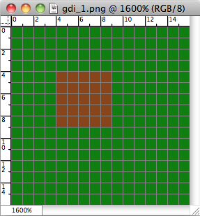
WindowWrite ( win , "C:/miniwindows/gdi_1.png" )


Now editing the resulting file (to save any possible problems with doing screen captures) in Photoshop, and zooming in, shows this:


Notice that the brown squares stop one short of the expected boundary, as the help for the API suggests it would.

Twisol said:

But (0,0,0,0) is supposed to mean the whole window area, no? If I use (0,0,201,251) it gets those last pixels, but that's counterintuitive, because the window is supposedly only 200x250.


It's nothing to do with that, as you can see. It happens for any size rectangle.

Interestingly, the comments are about SetWorldTransform changing the behaviour, and the new WindowTransformImage function does exactly that.

You can see that this behaviour affects all rectangles drawn with WindowCircleOp, not just ones going to the border, so for me to add 1 at this late stage is likely to throw out existing windows where people have, whether they realized why or not, compensated already.

So I think we'll leave it alone, but I'll put a note in the help for that operation.
Amended on Sat 28 Aug 2010 08:58 PM by Nick Gammon
USA #5
Nick Gammon said:
Interestingly, the comments are about SetWorldTransform changing the behaviour, and the new WindowTransformImage function does exactly that.

Since WindowTransformImage resets to the identity matrix right after, and it doesn't draw shapes (it only blits), I assume it's unaffected. Interesting though!

Nick Gammon said:
So I think we'll leave it alone, but I'll put a note in the help for that operation.

Sounds good, thank you.
Australia Forum Administrator #6
Twisol said:

Since WindowTransformImage resets to the identity matrix right after, and it doesn't draw shapes (it only blits), I assume it's unaffected. Interesting though!


Yes, correct. And I tested that the reference in the documentation was to other than the identity matrix (after all, it is unclear on that point).

My test seems to show that even after calling WindowTransformImage the results with the rectangle are the same.

Why on earth the graphics implementors made it draw an extra line of pixels if you happened to transform with a non-identity transformation eludes me somewhat.

Still, miniwindows have been out since July 2008, and you are the first person to notice that (and comment on it).
USA #7
One last related question. When I use WindowRectOp() and pass (0,0,0,0) or (0,0,width,height), it goes all the way to the edge. But I'm confused... I'd expect an image 100 pixels wide to go from 0 to 99. If I do (0,0,-1,-1) or (0,0,width-1,height-1), it misses one column/row.

Is this just another quirk of Windows GDI? It seems like it makes sense at first - from rect.Left to just before rect.Right, from rect.Up to just before rect.Bottom - but then WindowCircleOp really looks odd.

Anyways, this isn't a bug report now, I'm just mildly confused about the indexing. :S
Australia Forum Administrator #8
First comment, my test was wrong. After you call WindowTransformImage for some reason, it affected the next call to WindowCircleOp. So even the identify matrix affected it. I have set the mode back to GM_COMPATIBLE at the end of WindowTransformImage in order to keep compatibility with existing drawing, if you happen to transform an image somewhere in the code.
USA #9
Nick Gammon said:
Still, miniwindows have been out since July 2008, and you are the first person to notice that (and comment on it).


Do you mean the transform note or the WindowCircleOp offset thing? If the former, we haven't had a chance to use transforms on windows until yesterday, so it's not that surprising. If the latter, well... yeah, that's really surprising. :S

[EDIT]
Nick Gammon said:
First comment, my test was wrong. After you call WindowTransformImage for some reason, it affected the next call to WindowCircleOp. So even the identify matrix affected it. I have set the mode back to GM_COMPATIBLE at the end of WindowTransformImage in order to keep compatibility with existing drawing, if you happen to transform an image somewhere in the code.

I think it's the GM_ADVANCED setting that causes it, then, not the actual transformation. Bizzare!
Amended on Sat 28 Aug 2010 10:37 PM by Twisol
Australia Forum Administrator #10
Quote:

When I use WindowRectOp() and pass (0,0,0,0) or (0,0,width,height), it goes all the way to the edge. But I'm confused... I'd expect an image 100 pixels wide to go from 0 to 99. If I do (0,0,-1,-1) or (0,0,width-1,height-1), it misses one column/row.


OK, take a look at this:


Now the coordinates are the lines not the pixels. In my example I used this code this time:


WindowRectOp (win, miniwin.rect_fill, 4, 4, 10, 10, ColourNameToRGB("red"), 0)


So I am drawing from inside the rectangle bounded by 4 .. 10. That is, 6 pixels are filled (10 - 4).

Similarly if you are drawing inside a 100 pixel window, from pixel 0 to 100 I get 100 pixels. And if you pass 0 as the right-hand edge it replaces it by the window width (100 in your case).

The important point is that the coordinates are of the infinitely-thin points (or grid lines from the screenshot) not the coordinates of the pixels themselves.
USA #11
Nick Gammon said:
The important point is that the coordinates are of the infinitely-thin points (or grid lines from the screenshot) not the coordinates of the pixels themselves.


Oh. That completely explains it. Thanks so much, Nick!
Australia Forum Administrator #12
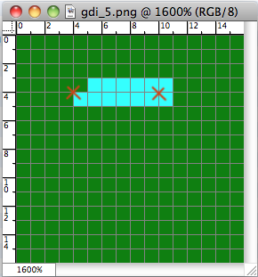
And take a look at this (I have marked the coordinates with Xs):


WindowLine (win, 4 , 4 , 10 , 4 , ColourNameToRGB("cyan"), miniwin.pen_solid , 1 )


Result:


That has drawn a single pixel line from 4,4 to 10,4 underneath the coordinate line.

However I admit I find this one a bit puzzling:


WindowLine (win, 4 , 4 , 10 , 4 , ColourNameToRGB("cyan"), miniwin.pen_solid , 2 )


(Notice the 2-pixel pen width). I can only assume the missing pixel is because it is trying to draw a slightly diagonal line. Also note that it overshoots the end coordinate because of the wider brush.

This looks better:


WindowLine (win, 4 , 4 , 10 , 5 , ColourNameToRGB("cyan"), miniwin.pen_solid , 2 )


I don't know whether to write this off to my lack of knowledge of graphics primitives, or to say "ah well, that's Windows for you".
Amended on Sat 28 Aug 2010 11:09 PM by Nick Gammon
USA #13
Try drawing with a 20-width pen. The effect is pretty obvious: it rounds the ends out.

[EDIT] Freaky! If you supply the same coordinates for the start and end points of WindowLine, it produces a circle because of this rounding effect. :D

Interesting way to draw "points" I suppose, eh?
Amended on Sat 28 Aug 2010 11:12 PM by Twisol
Australia Forum Administrator #14
Well looks like the rest of the day is going to be spent on this ... ;)

From the Windows API help:

Lines API said:

GDI uses a digital differential analyzer (DDA) to determine the set of pixels that define a line. A DDA determines the set of pixels by examining each point on the line and identifying those pixels on the display surface (or dots on a printed page) that correspond to the points.

...

The simplest and most common DDA is the Bresenham, or incremental, DDA. A modified version of this algorithm draws lines in Windows. The incremental DDA is noted for its simplicity, but it is also noted for its inaccuracy. Because it rounds off to the nearest integer value, it sometimes fails to represent the original line requested by the application. The DDA used by GDI does not round off to the nearest integer. As a result, this new DDA produces output that is sometimes much closer in appearance to the original line requested by the application.


It is certainly gratifying (excuse sarcasm) that the algorithm used by Windows "sometimes" draws lines closer in appearance to the ones requested.

BTW testing your suggestion for wider lines certainly partly confirms what you said, but for something like an 8-pixel wide line, the rounded ends don't look very good.
Amended on Sun 29 Aug 2010 05:35 AM by Nick Gammon
USA #15
Nick Gammon said:
Well looks like the rest of the day is going to be spent on this ... ;)

There's nothing I'd rather do than play with code. :D

Nick Gammon said:
It is certainly gratifying (excuse sarcasm) that the algorithm used by windows "sometimes" draws lines closer in appearance to the ones requested.

Rofl.

Nick Gammon said:
BTW testing your suggestion for wider lines certainly partly confirms what you said, but for something like an 8-pixel wide line, the rounded ends don't look very good.

Hmm, yes. It's only an approximation after all.
Australia Forum Administrator #16
Right, well this whole thing has turned out more complex than I imagined.

It seems we need control over the line end and join styles, something we didn't have before.

I have added another bitmask to the pen styles (where the default is what it always did, which was have a round end).

The results are a bit more obvious with large line widths.

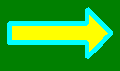
This is the code for a miter join:


local win = "win"
WindowCreate(win, 0, 0, 250, 150, miniwin.pos_center_all, 0, ColourNameToRGB "green")

WindowPolygon (win, "20,50,180,50,180,20,230,70,180,120,180,90,20,90",
                    ColourNameToRGB ("cyan"),  -- pen colour
                    miniwin.pen_solid + miniwin.pen_join_miter,  -- pen style
                    10,      -- pen width
                    ColourNameToRGB("yellow"),   -- brush colour
                    miniwin.brush_solid,         -- brush style
                    true,    -- fill
                    false)   -- alternate fill

WindowShow(win, true)


Results:


Now changing the style line for a round join:


                    miniwin.pen_solid + miniwin.pen_join_round,  -- pen style


Results:


And a bevel join:


                    miniwin.pen_solid + miniwin.pen_join_bevel,  -- pen style


Results:


Amended on Sun 29 Aug 2010 02:04 AM by Nick Gammon
USA #17
Slick! I didn't even realize that was possible. 4.59 will be a good release for miniwindows.
Australia Forum Administrator #18
And now line endings:


local win = "win"

WindowCreate (win, 0, 0, 100, 100, miniwin.pos_center_all, 0, ColourNameToRGB "green")

WindowLine (win, 20 , 40 , 50 , 40 , 
       ColourNameToRGB ("cyan"),  -- pen colour
       miniwin.pen_solid + miniwin.pen_endcap_flat,  -- pen style
       20)  -- pen width

WindowShow (win, true)


       miniwin.pen_solid + miniwin.pen_endcap_square,  -- pen style


       miniwin.pen_solid + miniwin.pen_endcap_round,  -- pen style


The difference between square and flat is whether the pen width overshoots the dimensions of the line (the round overshoots as well).

This shot in Photoshop shows that:


The red box is the requested width, and you can see that the line overshoots on either side (square, however) by half the pen size.